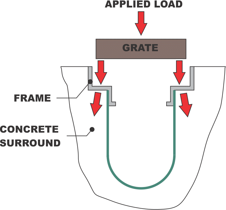
The flow path follows the fluids from the surface through the grating, down the channel, and out the piping system at the end of the drain. If any one of these components is not properly sized the system will not work to capacity. It is very common to see drains improperly sized because one of these three items was not properly evaluated. A correctly sized system is much more economical and can save significant cost on any project.
The grate should first be evaluated for inflow capacity. The grating is rarely the limiting factor in a design. The grating can be the limiting factor when the trench run is short, the grate has small openings, or large debris loads are expected to clog the grating. Here is a link to the grate open area page.
The channel body can be a limiting factor. The flow rate should be checked against the design flow. Note that trench width, depth, and slope of a Dura Trench system can be altered to ensure the flow rates match the design flow. Here is a link to the channel flow capacities page.
The outlet system is often overlooked and can be the limiting factor on the flow capacity of a channel drain system. In most cases, the outlet piping system should be designed to accept the design flow. The only time this is not the case is when the trench is used for settling out solids or as a storage / containment vessel.
SAMPLE PROBLEM: A parking lot will be sloped to a trench drain that will need to capture the rainfall during a 50 year storm. The parking lot is 1.8 acres in size and the trench drain will be 70 feet long. The rainfall intensity is 6.2 inches per hour. The drain will be near a cross walk so we will need an ADA compliant grate. There is minimal debris in the parking lot area and it is not a concern. What size trench drain should be used?
SOLUTION: Let’s start by simply determining the volume of water that needs to be captured. In this simplistic problem we will use Q = C I A where Q is the required flow in CFM, C is the runoff coefficient for asphalt, I is the rainfall intensity, and A is the area in acres.
Q = (0.9)*(6.2 in/hr) * (1.8 acres)
= 10.0 cfs
Following the flow path we will first select a grate that can capture the required hydraulic load. We need to calculate the required open area of the grate. To do this we will use the equation Q = Cd * A * (2*g*h)^0.5 where Q is the flow rate that is captured in cfs, Cd is a discharge coefficient usually assumed to be 0.6, A is the open area of the drain system, g is a gravitational constant (32 ft/sec/sec), and h is the head above the floor in feet. We will rearrange this formula to solve for the grate open area.
A = Q / (Cd * (2*g*h)^.5)
= 10 cfs / (0.6 * (2*32ft/sec/sec*.01ft)^0.5)
= 20.8 sq ft
=2995 sq in
Now we divide this number by the linear feet of trench drain to determine the open area required per linear foot of trench.
OA = 2995sq in/ 70 ft
= 42.8 sq in/ft
We can now use the tables of grates and look up a grate that has sufficient open area and is also ADA compliant. For this example we will assume we want a ductile iron grate for the vehicular load and need a “C” style grate to meet the ADA compliance. The smallest grate that will have the open area, load rating, and ADA compliant opening is the 12C24DI grate.
Next we must determine the channel flow capacity to ensure the channel can carry the required flow. The channel for a 12″ wide grate is 10″ wide. No trench body material was specified so we will utilize a standard prefabricated polymer trench. Using the channel flow capacity charts for 10″ wide trench drains we can look for a slope and depth combination that will handle the design flow (in this case 10 cfs). By using the channel flow data we see that a 10″ trench must be 36.5″ deep at 0.5% slope or 28″ deep at 1% slope to handle the flow volume of 10 cfs. In this case no depth restriction was given so either solution would work. If depth restrictions were a concern the width could be increased to reduce the depth.
Finally, the outlet pipe must be appropriately sized for the 10 cfs flow requirement. For this design we will assume the pipe has a 1% slope. With this assumption the pipe would need to be a minimum of 18″ in diameter. Dura Trench products can create pipe adapters for any size pipe to any size trench. The pipe can either be directly connected to the trench drain or the trench drain could flow into a catch basin that housed the pipe connection.

